
Architectural layout of DMX-based access control systems
Deploying an access control infrastructure over a DMX512 network architecture synchronizes physical locking actuators with visual status indications across commercial and entertainment facilities. Rather than installing disparate, parallel cabling runs for access control panels and architectural illuminations, DMX unifies command signals over a high-speed serial bus. Badge readers, biometric terminals, and push-to-exit buttons communicate their authentication events to central DMX controllers equipped with dry-contact trigger inputs.
This integration simplifies building infrastructure while providing real-time visual feedback at each doorway during ingress or egress cycles. The asynchronous serial protocol distributes continuous refresh frames to dedicated decoders and power switches situated near each monitored opening. Facility operators can map door strikes, magnetic locks, and RGB indicator strips to consecutive DMX channels, ensuring synchronized lock release and clear directional guidance for building occupants without noticeable processing latency.
Integrating credential readers with DMX trigger interfaces
Interfacing commercial RFID card readers, biometric scanners, and keypads with DMX automation hardware requires reliable signal conversion modules. Conventional physical access readers communicate via Wiegand, RS-485 OSDP, or simple relay closures. When an authorized credential is authenticated, the access reader energizes an output relay, generating a dry-contact closure that enters the programmable trigger ports of the primary DMX processing equipment.
The catalogue features the Euchips DMX-X03 touch panel controller, which operates from an Input Voltage of 5 V, draws an Output Current of 0.5-1 A, and processes Dim Mode DMX512/1990 signals. This device initiates programmed access sequences upon contact detection, altering channel output values instantaneously. Field technicians must consult device documentation to verify voltage tolerance limits on external contact terminals and ensure clean signal transitions without ground loops.
Deploying standalone and networked master DMX controllers
The central controller serves as the primary decision engine, governing frame generation and scheduling across all connected access control points. Depending on facility size and zone complexity, system architects deploy either DIN-rail standalone processors or networked controllers installed within central equipment racks. The master unit arbitrates between real-time reader inputs, scheduled lockdown sequences, and mandatory fire alarm override directives that mandate immediate perimeter unlocking.
For extensive installations requiring multi-universe scalability, the Euchips DMX-P08 provides 1024-channel live and stand-alone DMX512 controller capability powered by an Input Voltage of 5 V. Its non-volatile internal memory preserves sequence logic and channel assignments through sudden power interruptions. Engineers must examine technical datasheets to establish proper universe segmentation, preventing traffic saturation and guaranteeing deterministic transmission times for life safety and physical security commands.
Driving electromagnetic locks and relays via DMX decoders
Physical barrier hardware such as magnetic shear locks, electric door strikes, and motorized turnstile latches requires switched DC power currents far exceeding logic-level bus capacity. DMX decoders translate received packet bytes into pulse-width modulation or discrete transistor switching to actuate auxiliary relays. Coordinated channel mappings allow the system to drop holding voltage on magnetic locks while concurrently altering illumination around the door frame.
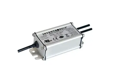
The LTECH LT-811-12 A 1-channel constant voltage DMX512 decoder accepts an Input power of DC12V~DC24V, providing a Max Load Current of 12 A ×1CH + 0-10 V ×1CH + 10 V PWM ×1CH and Max Output Power of 144 W/288 W/(12 V/24 V) with a Dimming Range of 0~100%. For integrating analog door operators, the Inventronics CNV-DMXR converts DMX to 0-10 V dimming signal, includes CAN bus Yes functionality, and meets IEC 61347-1 and IEC 61347-2-11 standards.
Software configuration and channel mapping for access events
Software configuration defines how access events trigger output channel states across the DMX universe. Each controlled access point receives a dedicated block of DMX addresses configured within the controller software matrix. The initial channel typically commands the power stage of the lock release relay, while subsequent channels control RGB status luminaires to display red for standby and green for granted clearance.
Programming tools allow commissioning personnel to define precise hold-open duration timers, commonly set between three and eight seconds following authorized badge detection. Digital output thresholds must be calibrated accurately: a zero value de-energizes fail-safe locks to open the door, whereas a full value of two hundred fifty-five restores magnetic holding force. System programmers must verify failsafe behavior under power loss conditions within the configuration software before commissioning.
Differential RS485 cabling and power distribution rules
Maintaining signal integrity across a DMX512 infrastructure demands adherence to strict physical cabling practices. Installers must route shielded twisted-pair cabling in a continuous daisy-chain topology from the master controller to every decoder, avoiding untruncated tee connections or passive star splits. A standard one hundred twenty ohm termination resistor must bridge data lines at the final receiver to absorb signal reflections that cause erratic triggering.
Separating low-voltage DC power runs from differential data conductors prevents magnetic coil flyback pulses from corrupting serial communications. When inductive door lock coils disengage, high-voltage spikes can disrupt digital decoders unless clamping protection diodes are installed directly across lock terminals. Installers must calculate conductor gauge requirements according to maximum current draw to prevent operational failure caused by excessive voltage drop over extended cable spans.
Step by step
1. Siting access credential readers and master controllers
Mount badge readers and keypad terminals adjacent to controlled entrances according to accessibility height standards. Connect dry-contact reader outputs to the programmable input terminals on the master DMX controller. Review the manufacturer documentation to confirm line polarity and maximum acceptable voltage limits on the trigger lines.
2. Wiring the differential DMX512 communication trunk
Run shielded twisted-pair cable with a characteristic impedance of one hundred twenty ohms connecting the master controller to all decoders in a continuous daisy-chain topology. Avoid unbuffered star taps. Install a one hundred twenty ohm termination resistor across the Data Plus and Data Minus terminals at the final decoder on the line.
3. Connecting power decoders and auxiliary locking circuits
Connect external twelve or twenty-four volt DC power supplies to the decoders assigned to electromagnetic locks and status lights. Install a flyback protection diode across the terminals of each inductive lock coil to suppress transient voltage spikes. Check cable conductor gauges against maximum current draw to prevent operational failures.
4. Mapping DMX channels and programming trigger sequences
Assign distinct start addresses to each decoder, allocating separate channels for lock coil switching and door status indicators. Configure release duration timers between three and eight seconds within the controller software interface. Confirm that a zero channel value de-energizes fail-safe locks to permit unrestricted egress.
5. Commissioning switching thresholds and fail-safe behavior
Execute a complete authentication cycle with an authorized credential to verify that the red status indicator transitions to green while the locking magnet releases. Simulate a complete power loss to confirm that all locking hardware drops holding force immediately, ensuring compliance with emergency exit safety standards.
Frequently asked questions
Why use a DMX bus rather than a traditional physical access controller?
Utilizing the DMX protocol unifies physical locking actuation with architectural directional lighting across a single communication bus. This architecture simplifies cabling runs in public venues and commercial spaces while reducing the number of disparate field controllers required for access monitoring.
How do you protect DMX decoders from inductive voltage spikes generated by door locks?
De-energizing electromagnetic lock coils generates severe inductive flyback spikes. Installing a clamping diode directly across the terminals of each lock coil suppresses these transient voltages, while routing DC power lines away from differential DMX data lines prevents signal corruption.
What occurs if communication along the DMX512 line is interrupted?
Industrial DMX decoders feature programmable fallback behavior when signal loss is detected. For designated egress doors, decoders should be configured to drop output power upon signal loss, allowing fail-safe magnetic locks to release automatically to satisfy building evacuation requirements.
Products mentioned
DMX-X03
DMX Controllers
Standalone and networked DMX controller with touch screen · Ref. : DMX-X03

- DMX512/1990
- DMX-X03
- 0.5-1
Price on request
DMX-P08
DMX Controllers
1024-channel live and stand-alone DMX512 controller · Ref. : DMX-P08

- DMX-P08
Price on request
CNV-DMXR
DMX Controllers
DMX to 0-10V dimming signal converter
- Notes
Price on request
LT-811-12A
DMX Controllers
1-channel constant voltage DMX512 decoder · Ref. : LT-811-12A
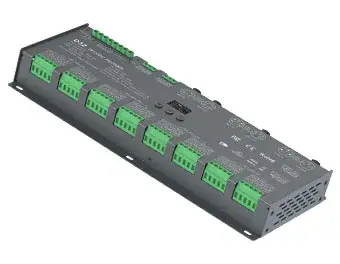
- L175×W44×H30(mm)
- 0~100%
- DC12V~DC24V
Price on request
A project? Our engineers build the solution with you.
Send your requirements: Atlas proposes the architecture, the bill of materials and a quotation, then follows the supply.
Request a quotation