
Physical layer operation of HART under IEC 61158, IEC 61784, and protocol specifications
The HART protocol superimposes a digital frequency-shift keying signal based on the Bell 202 standard onto a standard 4-20 mA analog current loop. A logic 1 is transmitted at 1200 Hz and a logic 0 at 2200 Hz at a raw data rate of 1200 bits per second. Because the ±0.5 mA sine wave has a zero average DC value, the underlying analog process variable remains undisturbed for the PLC or controller.
Its protocol stack is aligned with IEC 61158 for industrial fieldbuses, IEC 61784 for communication profiles, and the official HART Communication Protocol Specification. A streamlined three-layer model spans the physical layer, a master-slave data link layer using structured frames, and an application layer organizing universal commands, common practice commands, and device-specific commands paired with electronic device description files.
Electrical and network topologies from 4-20 mA point-to-point to WirelessHART
In point-to-point wiring, a single field instrument connected over a shielded twisted pair carries the primary measurement as a 4-20 mA DC signal while digital frames transport diagnostics and secondary variables. The bus supports two active masters concurrently: a primary master such as a distributed control system or PLC, and a secondary master such as a handheld field communicator temporarily clipped across the loop terminals.
When fast analog control is unnecessary, multidrop wiring connects up to 63 devices in parallel on one cable pair by fixing each transmitter output at 4 mA and polling individual addresses digitally. Alongside wired loops, WirelessHART defined in IEC 62591 establishes a self-organizing 2.4 GHz ISM mesh network using time-synchronized TDMA channel hopping to bring remote process points back to plant hosts.
Checking HART revision compatibility between field instruments and host systems
Before commissioning, engineers must check the HART revision supported by both the field transmitter and the host I/O subsystem or asset management server. Differences across HART 5, HART 6, and HART 7 affect extended command sets, multi-variable burst mode scheduling, and long tag addressing. When an older host polls a newer transmitter without matching revision support, extended device status flags and secondary dynamic variables may go unread.
Datasheets and engineering libraries must also be inspected to confirm availability of matching DD, EDD, or FDI device description packages for the exact firmware revision of the instrument. Without a matching device description imported into the engineering workstation, host communication drops back to basic universal commands, preventing configuration of damping, engineering units, diagnostic thresholds, or trim routines from the control room.
Loop impedance limits and minimum voltage drop across the communication resistor
Reliable FSK communication requires total loop resistance between 230 ohms and 1100 ohms, combining the precision communication resistor in series with the analog input card and the series resistance of field wiring. Below 230 ohms, the ±0.5 mA current modulation cannot develop enough peak-to-peak voltage swing for a HART modem to decode incoming frames accurately, causing intermittent timeouts or failed device polls.
Conversely, excessive resistance starves the transmitter of terminal voltage at maximum loop current of 20 mA or 22 mA fault alarm levels. Buyers must check the minimum supply voltage in the instrument datasheet and verify that the 24 V DC loop power supply accommodates the voltage drop across the 250 ohm resistor, intrinsic safety barriers, input module impedance, and cable resistance.
WirelessHART gateway interoperability, battery lifespan, and integration mistakes
In WirelessHART deployments, seamless interoperability between field nodes and the mesh gateway hinges on IEC 62591 revision alignment, join key provisioning, and host-side protocols such as Modbus TCP or OPC UA. Expected battery operating lifespan depends directly on the configured burst update rate, the number of neighbor hops each node relays within the mesh, and ambient temperature extremes recorded on site.
Frequent integration mistakes include operating loops below 230 ohms, wiring a transmitter straight to a power supply without a series resistor, grounding cable shields at both ends and inducing ground loops, or exceeding maximum cable capacitance and attenuating the 2200 Hz carrier. Installing standard non-HART galvanic isolators in hazardous areas also strips the FSK modulation completely before reaching the control cabinet.
Selecting industrial pressure, level, and temperature transmitters for plant loops
Across process skids combining Industrial Pressure Transmitters (4-20 mA / IO-Link), Level Transmitters, and Temperature Transmitters, hardware is supplied on quotation after reviewing datasheet parameters. For pressure loops, Microsensor MPM489 delivers ±0.25%FS, ±0.5%FS, ±1%FS accuracy with a 316 SS flush diaphragm, DN25DN100, 1 in 4 in flange diameter, and 4 mA 20 mA DC output, whereas Microsensor MDM483DM provides ±0.1%FS, ±0.25%FS, ±0.5%FS across -1 bar...00.1 bar…1000 bar.
For tank and sump monitoring, Microsensor MPM426WS covers 0 mH 2 O 2 mH 2 O…200 mH 2 O with 4-20 mA output, Holykell ULTRASONIC-LEVEL-SENSOR combines 4-20 mA and RS-485 Modbus RTU with a 12 beam angle, and Seeed Studio 314990619 offers IP68 protection and ± 0.25%F.S accuracy. When integrating these sensors behind HART converters or WirelessHART adapters, check output compatibility and power budgets in each datasheet.
Frequently asked questions
Why does a HART loop require at least 230 ohms of series resistance?
The HART modem senses voltage variations generated by the ±0.5 mA FSK current signal across the loop impedance. Below 230 ohms, the resulting voltage amplitude is too small for reliable decoding; a 250 ohm resistor is standard, while total loop impedance must stay below 1100 ohms.
Can two HART masters operate simultaneously on the same 4-20 mA loop?
Yes, the data link layer supports one primary master, typically the PLC or DCS analog input subsystem, and one secondary master, such as a handheld configurator. Timing rules separate their transmissions so both can poll the transmitter without frame collisions.
How can 4-20 mA or RS-485 transmitters connect to a HART supervision layer?
Devices providing 4 mA 20 mA DC or RS-485 Modbus RTU outputs, such as Microsensor MPM489 or Holykell ULTRASONIC-LEVEL-SENSOR, can be wired into a WirelessHART adapter or protocol converter, provided loop voltage drop and output ratings are checked in the datasheet.
What parameters most affect battery lifespan on a WirelessHART field node?
Battery operating lifespan drops sharply when publish intervals are shortened to a few seconds, when the device acts as a routing parent for multiple downstream neighbors, or when ambient temperatures sit near the battery chemistry limits.
Products mentioned
ULTRASONIC-LEVEL-SENSOR
Level Transmitters
Ultrasonic level sensor with 4-20 mA and RS485 Modbus RTU

Price on request
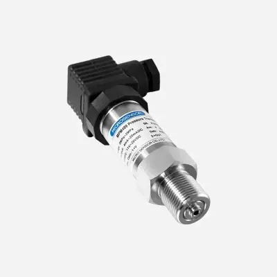
MPM489
Industrial Pressure Transmitters (4-20mA / IO-Link)
ATEX pressure transmitter with flush diaphragm · Ref. : MPM489
- *
- DN25~DN100, 1-in~4-in
- 316 SS
Price on request
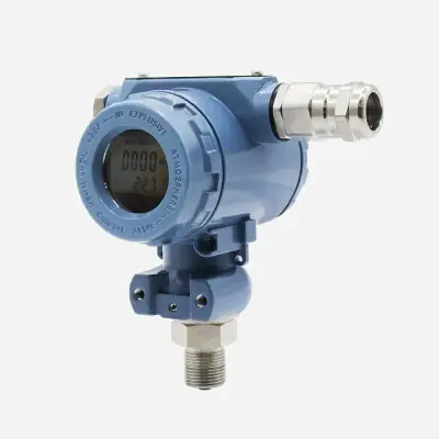
MPM483DM
Industrial Pressure Transmitters (4-20mA / IO-Link)
Explosion-proof digital pressure transmitter · Ref. : MDM483DM
- *
- DN25~DN100, 1-in~4-in
- 316 SS
Price on request
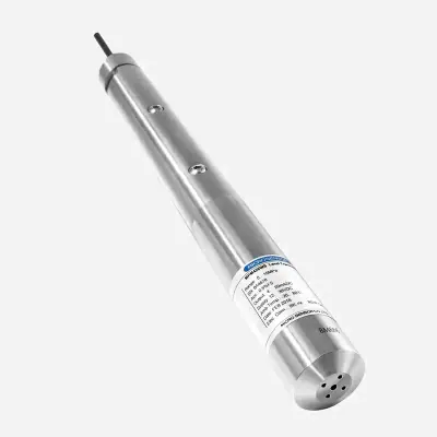
MPM426WS
Level Transmitters
Deep-water level transmitter with 4-20 mA output · Ref. : MPM426WS
Price on request
314990619
Level Transmitters
Liquid Level Sensor for Water Level, Oil Level and Mild-corrosive Liquid Level Monitoring

- ± 0.25%F.S
- 5.3 meters
- CE, FCC, RoHS
Price on request
A project? Our engineers build the solution with you.
Send your requirements: Atlas proposes the architecture, the bill of materials and a quotation, then follows the supply.
Request a quotationRelated pages
 Wiki4-20 mA current loop: what it is and how it is usedTechnical definition, operating principles, industrial standards, and datasheet selection criteria for hardware integration projects supported by Atlas engineers.
 WikiHART: what it is and how it is usedUnderstand the HART protocol, FSK modulation over 4-20 mA loops, HART revisions, industrial use cases, and key datasheet checks before quoting.
 Project4-20 mA Process Sensors: Pressure, Level & Flow MetersB2B technical guide for specifying 4-20 mA pressure transmitters, level sensors and industrial flow meters for supply on quotation.
 ArticleHow does a 4-20 mA transmitter work? Loop power and wiring rulesUnderstand how a 4-20 mA transmitter works, 2 wire vs 3/4 wire wiring, 250 ohm loop budget calculations, and live-zero fault signaling.