
Definition and Fundamental Operating Principle of the 4-20 mA Standard
The 4-20 mA current loop remains the benchmark analog signaling standard for transmitting field sensor measurements across industrial environments. Rather than using variable voltage levels that degrade over long distances, this method modulates electric current along a closed circuit. The physical zero of the process variable corresponds to a regulated current of 4 mA, while the full scale of the instrumentation corresponds to 20 mA.
This linear conversion provides strong immunity against electromagnetic noise from variable frequency drives, switching gear, and large induction motors. Because current remains identical at every point in a series circuit regardless of cable length, resistance drops do not corrupt data accuracy. The transmitter dynamically adjusts its internal resistance to maintain exact current levels, ensuring dependable process readings at the automation controller.
The Live Zero Concept and Fault Diagnostics in 4-20 mA Current Loops
Assigning a 4 mA baseline to the bottom of the measurement range introduces the essential concept of a live zero. This explicit offset separates a legitimate zero measurement from a dead circuit condition where no power or signal flows. When a sensor monitors an empty tank or neutral atmospheric pressure, it still actively drives exactly 4 mA through the loop to confirm operational continuity.
If a cable breaks, a terminal comes loose, or an instrument loses power, the loop current immediately drops to 0 mA. The programmable logic controller detects this sub 4 mA state as a hardware fault rather than mistaking it for a valid low-end measurement. Furthermore, advanced diagnostic standards register currents above 20.5 mA or below 3.6 mA to indicate transducer saturation or internal component failures.
Two-Wire, Three-Wire, and Four-Wire 4-20 mA Loop Topologies
Industrial current loop wiring falls into three primary topologies determined by field device power demands and circuit isolation needs. The two-wire topology, commonly known as a loop-powered connection, is the dominant architecture across processing facilities. In this configuration, the same pair of conductors delivers direct-current excitation to the transmitter and carries the variable 4-20 mA measurement signal back to the receiver card.
Three-wire configurations utilize a shared common ground between the external power supply and the output signal line. Four-wire transmitters, or self-powered units, completely isolate the alternating or direct current supply lines from the measurement loop conductors. This four-wire setup suits heavy-duty devices equipped with internal heating elements or digital displays, giving engineers flexible wiring choices based on available cabinet infrastructure.
Maximum Load Calculation and Electrical Sizing for 4-20 mA Loops
Accurate operation of a 4-20 mA loop requires calculating the total loop resistance to ensure the power supply provides sufficient terminal voltage. The direct-current power source, typically rated at 24 V DC, must overcome voltage drops across every series element under full load. These elements include the transmitter minimum operating voltage, the wiring resistance across extended cable runs, and the input impedance of the receiver.
A standard 250 ohm precision resistor at the receiver converts the 4-20 mA current into a 1 to 5 V DC signal for analog-to-digital conversion. If cumulative loop resistance exceeds the allowable compliance limit at 20 mA, the current signal clips prematurely before reaching full span. System integrators must verify the maximum load resistance formula in the product documentation during the engineering design phase.
Industrial Pressure and Level Transmitters Operating on 4-20 mA
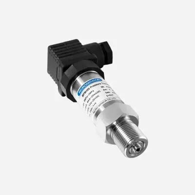
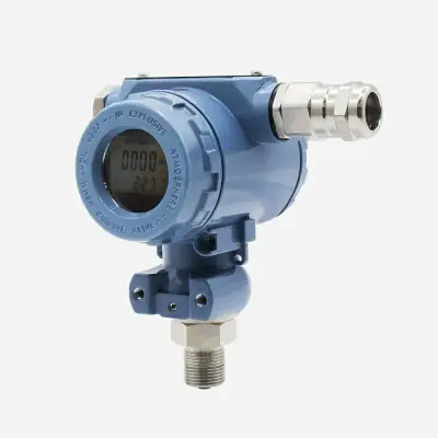
Industrial field instruments illustrate the versatility of the 4-20 mA current standard across process monitoring duties. Within the Industrial Pressure Transmitters (4-20 mA / IO-Link) family, the Microsensor MPM489 transmitter features a 4 mA 20 mA DC output with a 316 SS Flushing ring and an Accuracy of ±0.25%FS, ±0.5%FS, ±1%FS. For severe pressure ratings, the Microsensor MDM483DM unit provides a 4 mA 20 mA DC signal, an Accuracy of ±0.1%FS, ±0.25%FS, ±0.5%FS, and a wide Range spanning -1 bar...00.1 bar…1000 bar.
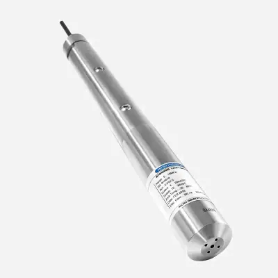
In the Level Transmitters category, the submersible hydrostatic probe Microsensor MPM426WS outputs 4-20 mA for continuous monitoring over a Level measurement range of 0 mH 2 O 2 mH 2 O…200 mH 2 O with an Accuracy of ±0.25%FS, ±0.5%FS, ±1%FS. For non-contact tank gauging, the Holykell ULTRASONIC-LEVEL-SENSOR transmitter pairs a 4-20 mA interface with RS-485 Modbus, featuring a 12 Beam Angle and a Min. operating temperature of -10 °C.
Datasheet Evaluation Criteria for Industrial 4-20 mA Transmitters
When evaluating a manufacturer datasheet for a 4-20 mA transmitter, engineers must examine the excitation supply voltage window. This specification indicates the minimum voltage needed across device terminals to maintain regulation, especially when running long cable runs from a 24 V DC supply. Technical datasheets typically provide a load diagram outlining the maximum allowable loop resistance as a function of available supply voltage.
Other critical parameters include overall accuracy classes, ambient temperature drift coefficients, and analog output response times under dynamic process conditions. Buyers must verify fault signaling limits, confirming whether the device adheres to standards by clamping fail-low or fail-high states. Verifying environmental protection ratings and reverse-polarity safeguards ensures robust hardware integration inside control enclosures and remote terminal units.
Frequently asked questions
What is the main operational difference between two-wire and four-wire 4-20 mA transmitters?
A two-wire transmitter uses the same wire pair for both DC power supply and loop current signaling, reducing installation cabling. A four-wire transmitter separates power input from the analog output loop, accommodating devices with higher power consumption.
Why does the 4-20 mA industrial standard use 4 mA as the lower measurement baseline?
The 4 mA baseline represents a live zero, allowing controllers to differentiate between a zero-scale process reading and a cut wire or power failure. If loop current falls to 0 mA or drops below 3.6 mA, the system immediately triggers a fault diagnostic.
How is a 4-20 mA current signal converted into voltage for an analog input card?
A high-precision 250 ohm resistor is installed in series across the receiver input terminals. Applying Ohm’s law, a current of 4 to 20 mA generates a standardized 1 to 5 V DC drop that analog-to-digital converters read directly.
How does cable length affect a 4-20 mA current loop compared to voltage signaling?
Because current is conserved throughout a closed series loop, wire resistance does not cause measurement signal attenuation over long runs. As long as the excitation power supply voltage satisfies the compliance load equation, transmission over several hundred meters remains precise.
Products mentioned
ULTRASONIC-LEVEL-SENSOR
Level Transmitters
Ultrasonic level sensor with 4-20 mA and RS485 Modbus RTU

Price on request
MPM489
Industrial Pressure Transmitters (4-20mA / IO-Link)
ATEX pressure transmitter with flush diaphragm · Ref. : MPM489
- *
- DN25~DN100, 1-in~4-in
- 316 SS
Price on request
MPM483DM
Industrial Pressure Transmitters (4-20mA / IO-Link)
Explosion-proof digital pressure transmitter · Ref. : MDM483DM
- *
- DN25~DN100, 1-in~4-in
- 316 SS
Price on request
MPM426WS
Level Transmitters
Deep-water level transmitter with 4-20 mA output · Ref. : MPM426WS
Price on request
A project? Our engineers build the solution with you.
Send your requirements: Atlas proposes the architecture, the bill of materials and a quotation, then follows the supply.
Request a quotationRelated pages
 WikiHART: what it is and how it is usedUnderstand the HART protocol, FSK modulation over 4-20 mA loops, HART revisions, industrial use cases, and key datasheet checks before quoting.
 ArticleUnderstanding HART: architecture, standards & hardwareTechnical guide to the HART protocol: IEC layers, 4-20 mA and WirelessHART topology, loop impedance checks, pitfalls, and field instruments.
 Project4-20 mA Process Sensors: Pressure, Level & Flow MetersB2B technical guide for specifying 4-20 mA pressure transmitters, level sensors and industrial flow meters for supply on quotation.
 ArticleHow does a 4-20 mA transmitter work? Loop power and wiring rulesUnderstand how a 4-20 mA transmitter works, 2 wire vs 3/4 wire wiring, 250 ohm loop budget calculations, and live-zero fault signaling.